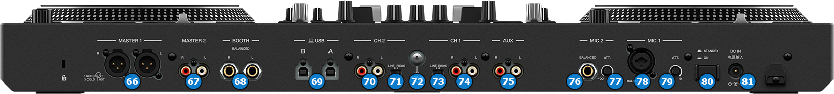
MASTER OUT1: Master signal output connectors (XLR – Balanced). Use this to connect on your pro grade amplifier or self-powered speakers.
MASTER OUT2: Master signal output connectors (RCA – Unbalanced). Use it to connect with another mixer, or consumer grade amplifier.
BOOTH OUT: Booth signal output (TRS – Balanced). The strength of the signal is controlled by “BOOTH VOL” knob (26) on the top panel. Use it to connect your booth speakers, or an amp that needs different sound output level than master output.
USB CONNECTORS: Use a standard USB cable to connect DDJ-REV7 with your computer.
CH2 INPUT: Connect an analog source on CH2 of the DDJ-REV7 mixer. You can connect a turntable or a CD-Player. The input is selectable via “SOURCE SEL” switch (25) on the top panel.
CH2 INPUT TYPE: Select whether the device connected on CH2 analog inputs provides a line or phono level signal.
GND SCREW: Use it to screw your GND (ground) cable from turntables that provide it in order to eliminate GND static noise.
CH1 INPUT TYPE: Select whether the device connected on CH1 analog inputs provides a line or phono level signal.
CH1 INPUT: Connect an analog source on CH1 of the DDJ-REV7 mixer. You can connect a turntable or a CD-Player. The input is selectable via “SOURCE SEL” switch (25) on the top panel.
AUX INPUT: Connect an analog source on the AUX input of the DDJ-REV7 mixer. You can only connect a line level device here. The sound of the device is routed directly to the master audio output of DDJ-REV7 and you can only control it's level via the the "AUXILIARY INPUT VOL" knob (65) on the front panel.
MIC 2 INPUT: Connect a mic on the DDJ-REV7mixer. You can use only a Jack (TRS) connector.
MIC 2 ATT: Adjust the attenuation (gain) of the MIC2 input.
MIC 1 INPUT: Connect a mic on the DDJ-REV7 mixer. You can use XLR or Jack (TRS) connectors.
MIC 1 ATT: Adjust the attenuation (gain) of the MIC1 input.
POWER SWITCH: Turns on/off the power on the device. Please turn on the device only after doing and securing all connections on the back.