


DJC-4
FRONT & REAR PANELS
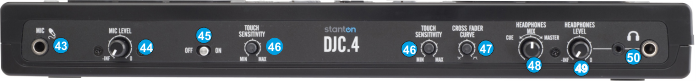
- MIC INPUT. Connect a Microphone to this Input.
- MIC LEVEL. Adjust the Volume of the Microphone Input of the Stanton DJC.4
- MIC ON. Turn On/Off the Microphone Input of the unit.
- TOUCH SENSITIVITY. Use these knobs to adjust the touch sensitivity of the left and right jogwheels.
- XFADER CURVE. Adjusts the slope of the crossfader curve. Turn the knob to the left for a smooth fade (mixing) or to the right for a sharp cut (scratching). The center position is a typical setting for club performances.
- HEADPHONES MIX: Turn to mix between Cue and Master in the Headphone channel. When all the way to the left, only channels routed to Cue will be heard. When all the way to the right, only the Master Output will be heard.
- HEADPHONES LEVEL. Adjusts the volume level of the headphone output.
- HEADPHONES SOCKET. Connect your 1/4" headphones to this output for cueing and mix monitoring.
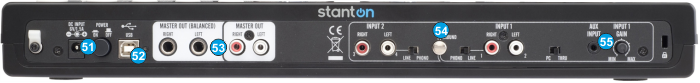
Stanton DJC4 Rear Panel - POWER: While the DJC.4 can run very comfortably with USB bus power, in cases where your computer may not supply enough USB bus power, it may be necessary to connect an additional power supply. Use a proper power 6V DC adaptor to connect Stanton DJC.4 to a power outlet.
- USB. This USB connection sends and receives audio and control information from a connected computer.
- MASTER OUTPUT (TRS/RCA): Use standard RCA or TRS cables to connect this output to a speaker or amplifier system. The level of this output is controlled by the Master knob on the top panel.
- LINE INPUTS. Connect your audio sources to these inputs and can accept both line and phono-level signals.
Use the PC/THRU switcher to send all Inputs directly to the master out (THRU) and mute the software output or to VirtualDJ (PC). See Advanced Setup - AUX. CD players, MP3 Player, Tablet Pad and other line level instruments may only be connected to this jack. Input volume will be controlled by the channel fader. The channel INPUT1 (11) selector switch must be in the "AUX".