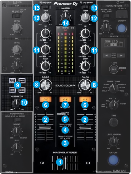
CROSSFADER. Blends audio between the left and right channels/decks.
VOLUME. Use these faders to adjust the Output Volume of each mixer channel.
CROSSFADER REVERSE. Set to ON to enable the reverse Crossfader behavior. When enabled, only Left Deck will be output at far right CF position and vice versa.
CROSSFADER CURVE. Select one of the 3 available slopes for the Crossfader
EQ CURVE. Select one of the 2 curves for the Equalizer (normal or Full Kill)
CUE. Use these buttons to send one or more channel's pre-fader signal to the Headphones Channel for monitoring. When engaged, the button will be lit.
MASTER CUE. Use this button to send the signal from the Master Output to the Headphones channel
COLOR FX KNOBS. Use these knobs to adjust the amount of the selected Sound Color Effect to each of the Mixer channels. No Effect is applied when the knob is at 12 o’clock position. Even though the COLOR knobs will move the FILTER knobs of the VirtualDJ GUI, the Color FX of VirtualDJ is still not applied (only provide a visual indicator)
COLOR BUTTONS. Use these buttons to select one of the 4 available Sound Color Effects (Noise, Filter, Echo and Sweep). Only one Color FX can be selected each time. The Color Effects are Hardware Effects and do not control any internal VirtualDJ Effect.
COLOR FX PARAMETER. Use this knob to adjust the offered Parameter of the selected Color FX (e.g. the Resonance of the Filter Color FX)
EQ HI/MID/LOW. Use these knobs to adjust the high (treble) / middle (mid) / low (bass) frequencies of each mixer channel.
TRIM. Adjusts the input audio level (gain) up to +9db of each mixer channel. No boost or cut is at 12 o’clock position.
INPUT SELECT. Set this switcher to the appropriate position to define which Channel Input will be routed to the 2 Mixer Channel Outputs
Set to USB position to route a VirtualDJ deck output to a mixer channel.
On PHONO/LINE positions the audio signal from the Inputs 1, 2 and 3,4 at the rear panel) will be routed directly to the Output of CH1 and CH2 Mixer Channels respectively. In this case the sound from the computer’s decks will be muted. Use this position to route external analogue media sources. Set to USB position to use a Timecode (DVS) system.
MASTER LEVEL. Use this knob to control the Output level of the Master Output.